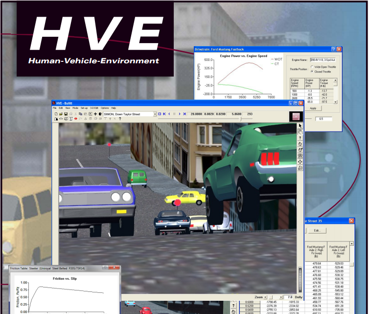
 HVE 肇事重建模擬軟體
HVE 肇事重建模擬軟體 HVE 碰撞模擬軟體係由美國 Engineering Dynamics Corporation 所發展的一套車輛 3D 碰撞模擬軟體,此一系統已有國外多次驗證其模擬結果的正確性,可提供3D立體車輛碰撞重建及模擬分析,分析車種除了小客車之外,尚可包括大貨車與大客車等多種車種,該系統亦提供道路幾何特性之設定功能。軟體內建多個關鍵模擬模組,可直接模擬兩車碰撞之過程、利用車損或撞擊 與最終位置利用線性動量守恆公式推估兩車碰撞時速度、藉由輸入不同參數,預測單一車輛造成失控之原因等,目的皆在提供車輛設計工程師、安全研究人員或道路交通事故重建人員一實用的分析工具。
Using HVE, you can . . .
- Simulate vehicle rollovers including exterior damage.
- Simulate the response of multiple occupants during a rollover collision including contact between the occupants.
- Simulate a crash sequence, change the initial conditions to study avoidability and route both results directly to video showing multiple views including the driver of each vehicle.
- Use virtual thermocouples to monitor brake lining temperatures on a downhill grade.
- Use virtual accelerometers to monitor the velocity and acceleration at any location in the vehicle.
- Simulate the transient response of a vehicle before, during and after a tire blowout.
- Study the effect of occupant positioning on restraint system effectiveness.
- Create a complex 3-D terrain mesh and drive a vehicle on it.
- Use the HVE Path Follower to simulate the driver steering inputs required to negotiate a complex curve.
- HVE is a Virtual 3-D World — HVE models humans, vehicles and the environment as sophisticated 3-dimensional objects and allows you to study their interaction. HVE makes virtually no simplifying assumptions.
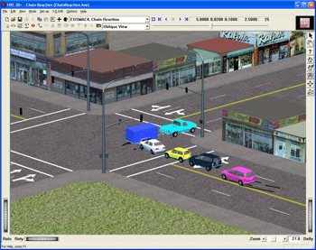
The above sequence used EDSMAC4 to simulate a crash involving 3 vehicles. The
damage profiles are visualized directly from the EDSMAC4 simulation results. The green car's post-impact rollover and resulting body damage were simulated using EDVSM. EDVDS was used to simulate the braking and steering dynamics of the tractor-trailer in a downhill curve.
One and a half miles of the crash site in the Columbia River Gorge were surveyed using a total station, edited using a 3-D CAD program, and imported into HVE. The vehicles' tires and bodies interact directly with the resulting surface mesh.
- HVE is a Visualization Tool — The human mind has difficulty interpreting the meaning of voluminous amounts of numerical data generated by a simulation. By comparison, the human mind easily comprehends vast amounts of visual data. Using HVE 3-D viewers, you can quickly and easily visualize the meaning of the information within HVE's numerical results.
The above crash sequence was simulated using EDSMAC4. With no additional work, the cause of the crash was obvious by replaying the simulation with HVE's virtual camera attached to the witnesses and driver of each vehicle. HVE's 3-D viewers allow you to zoom, dolly, pan and even spin the entire world.
- HVE is an Integrated Solution — HVE saves you enormous amounts of time by integrating the 3-D simulation environment, animation controller, 3-D modeler and video codec interface into one system. Simulations can be recorded to videotape, CD or DVD depending upon your equipment.
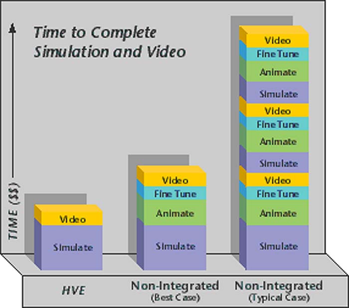 When you complete your simulation in HVE, you are ready to produce a movie file. This makes HVE a very cost-effective presentation tool for every simulation. Non-Integrated solutions often involve miscommunication, software compatibility problems and numerous iterations between the engineer and animator (such as keeping the tires in contact with a 3-D surface during the entire sequence)
- HVE is an Integrated Solution — HVE saves you enormous amounts of time by integrating the 3-D simulation environment, animation controller, 3-D modeler and video codec interface into one system. Simulations can be recorded to videotape, CD or DVD depending upon your equipment.
.jpg) In the simulation to the left, EDVDS was used to simulate an alternate ramp traversal test for studying suspension characteristics and frame torsional compliance. Other design applications include brake component and tire selection, and the general dynamic behavior of commercial vehicles pulling up to 3 trailers.
In the simulation to the left, EDVDS was used to simulate an alternate ramp traversal test for studying suspension characteristics and frame torsional compliance. Other design applications include brake component and tire selection, and the general dynamic behavior of commercial vehicles pulling up to 3 trailers.
- HVE is an Engineering Design Tool — Engineers can use HVE's robust human, vehicle and environment models to perform detailed parameter studies of individual components such as suspensions, drivetrains, tires and brakes. Vehicle handling behavior while driving over irregular terrain can be simulated to optimize your design. HVE provides a cost effective method for proving design concepts before expensive prototypes are produced.
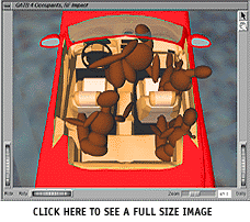 The GATB human simulation to the right involved four occupants in a passenger car. Not only did the occupants strike the vehicle interior, they also struck each other. The collision pulse for this occupant simulation was selected from the EDSMAC4 simulation of the two-car crash.
- HVE is Modular — HVE was engineered to allow you to extend its capabilities. You can choose a simulation model that is tailored to your specific needs, add custom databases, define your own units of measurement, select the number of decimal places in your input and output — you can even convert the program to French. You can use the HVE Developer's Toolkit to create HVE-compatible versions of any engineering model, including highly validated OEM engineering models used in the vehicle design process.
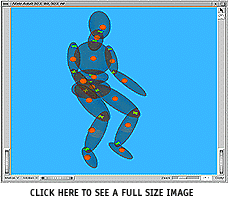

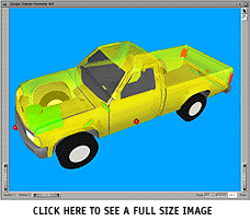
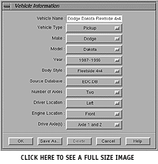
HVE's Human and Vehicle Editors allow you to select from a large assortment of fully defined 3-D human, vehicle and tire data sets in a standard hierarchical database. All properties may be edited using dialogs and viewers. Custom databases, such as EDVDB-3D, are also available containing data sets for specific vehicles (e.g. 1997 Ford Taurus 4-Dr sedan) and tires (e.g. Michelin P205/65R15 MXV4). Databases are user-extendable.
HVE ABS Simulation Model (Available in SIMON)
The HVE ABS Simulation model is a general purpose model, available for use in the SIMON vehicle simulation model. The model is applicable to the design of ABS systems, as well as the study of loss-of-control crashes of ABS-equipped vehicles. The HVE ABS model works like the ABS system on an actual vehicle: It uses an algorithm to modulate the brake pressure at each wheel. The algorithm is designed to maximize brake force and prevent excessive wheel slip.
Two ABS algorithms are currently implemented in the HVE simulation environment. These are the Tire Slip algorithm and the HVE Bosch Version 1 algorithm. Tire Slip - This is a simple and straight-forward ABS algorithm. Its design is based on the fundamental goal of an ABS system, which is to maintain tire slip in the vicinity of peak friction coefficient. It is generally applicable to any type of vehicle (passenger car, truck, etc). HVE Bosch Version 1 Algorithm - The HVE Bosch Version 1 ABS algorithm is based on the information provided in Bosch technical literature. The algorithm is based on wheel spin acceleration and a critical tire slip threshold. The Bosch ABS system is used on many US and foreign passenger cars.
To further enhance the results from an ABS simulation, HVE now includes a new method for displaying tire marks. In the new method, the opacity of a tire mark is varied according to the current vertical tire load (heavier tire loads produce darker marks), the percentage of longitudinal tire slip and the percentage of lateral tire slip (increased slip produces darker marks). In addition, a set of weighting coefficients determines the opacity of tire marks during combined braking and steering. Since the vast majority of vehicles are now fitted with ABS, the new HVE ABS model is an important new feature, especially for simulating pre-impact braking and loss of control.
More detailed information about the HVE ABS Simulation Model is available in SAE 2002-01-0559, "A Simulation Model for Vehicle Braking Systems Fitted with ABS" and in SAE 2010-01-0070, "Verification of ABS Models Applied in Programs for Road Accident Simulation".
HVE Brake Designer (Available in SIMON, EDVSM and EDVDS)
The HVE Brake Designer is a time-domain simulation model of user-defined brake system components. The purpose of the HVE Brake Designer is to provide a detailed brake design capability integrated directly within the HVE simulation environment. Engineers can reduce costs by performing simulated compliance tests of complete vehicles on a digital proving ground prior to expensive prototyping and proving ground testing. Examples include steering and braking on high-friction, low-friction and split-mu surfaces at different speeds and loading conditions. In addition, alternative brake designs can quickly be evaluated.
The HVE Brake Designer model incorporates advanced features, such as the effect of sliding speed and temperature on lining friction. The model also includes the capability to study brake fade characteristics, such as that which occurs to trucks on long downhill grades. Parameters defining physical, performance and material properties of brake components are fully user-editable.
Values for brake factor, actuation factor and brake torque ratio are calculated by the HVE Brake Designer. Initial values are based on the environment's ambient temperature and zero sliding velocity at the pad/rotor (or drum/lining) interface. During a vehicle dynamic simulation, the appropriate brake factor and brake torque ratio are based on the current brake internal temperature and sliding velocity calculated by the simulation. Outputs from HVE-compatible vehicle dynamics simulation models using the HVE Brake Designer include brake torque, brake stroke, brake pressure, brake piston force, drum/rotor temperature and lining temperature.
More detailed information about the HVE Brake Designer is available in SAE 2000-01-1294, "Integrating Design and Virtual Test Environments for Brake Component Design and Material Selection".
HVE Driver Model, Path Follower (Available in SIMON, EDVSM, EDVDS and EDSMAC4)
The HVE Driver Model is a closed-loop driver model, allowing users to define an attempted maneuver and have the simulation determine the required steering inputs to make the vehicle follow the defined path. Typical examples include single and double lane-change maneuvers. The HVE Driver Model may also be used to study the effects of driver fatigue and intoxication.
The HVE Driver Model has four components: Path Generator, General Parameters, Driver Descriptors, Driver Neuro-Muscular Filter. The path generator uses up to eight 3-D positions and orientations to define the attempted path. The path is constructed from a 3-D spline curve passing through each user-specified location and tangent to the roll, pitch and yaw orientations for each location. The general parameters provide control over the Driver Model algorithm. Control parameters include driver starting time, driver sample interval, driver preview distance, allowable path error, and initial steering wheel angle. The driver descriptors describe how the operator attempts to control the vehicle. These parameters include the driver preview distance (the point ahead of the vehicle where the driver is actually looking and presumably wants to go), driver comfort level (lateral acceleration), maximum steering wheel velocity, steer correction rate and steer correction damping. The driver neuro-muscular filter represents a mathematical model of the human operator in man-machine performance. The model used in HVE was derived from the model described by McRuer, et al (1965) as published in the NASA Bioastronautics Databook (NASA SP-3006). The model includes an effective time delay representing the time required to read, interpret and decide upon the appropriate control motion, the lead time representing a ratio of the weight the driver attributes to the displayed velocity compared to the displayed position, and the time lag representing the amount of data smoothing the driver applies to his external stimuli. These parameters correspond to the first-order effects of the neurological and muscular systems of a human driver.
More detailed information about the HVE Driver Model is available in SAE 2000-01-1313, "The Simulation of Driver Inputs Using a Vehicle Driver Model".
HVE Driver Model, Speed Follower (Available in SIMON)
SIMON users can take advantage of this enhancement to the HVE Driver Model. When assigning target positions for the Path Follower, simply assign a Total Velocity at each position in order to use the Speed Follower. SIMON will then determine the throttle and/or brake applications required to maintain the desired speed. The speed, just like the path, is determined using interpolation between target positions and velocities. The parameters that control the Speed Follower are found on the Speed tab in the HVE Driver Controls dialog. The main control parameters that define how quickly the pedals are applied and released are the Throttle and Brake Correction Rates.
HVE Steer Degree of Freedom Model (Available in SIMON and EDVSM)
The HVE Steer Degree of Freedom Model allows users to study how hands-off steering affects vehicle trajectory. The steering linkage of the vehicle is assumed to be rigid, thus the angular acceleration about the steering axis is the same for right-side and left-side wheels. External steer forces are generated at the tire-road interface, thus producing a moment about each tire's steering axis according to the tire's pneumatic trail. The moments are resisted by steer system inertia and internal coulomb friction. Steering is limited by right and left steering stops at each wheel. Based upon these conditions, the steering inputs used in the simulation are calculated from the interaction of the vehicle's tires traveling over and interacting with the 3-D terrain model defined by the user. An obvious application of the Steer Degree of Freedom Model is the post-collision motion of a vehicle.
HVE Tire Blow-out Model (Available in SIMON, EDVSM and EDSMAC4)
The output from the HVE Tire Blow-out Model provides detailed information regarding the transient nature of a vehicle's response to a tire blow-out that occurs during any maneuver. Dynamic changes in tire forces and moments are calculated and displayed, giving researchers the capability to simulate and predict the outcome for one or more driving scenarios, and to study how these transient forces affect vehicle handling.
To study transient effects, the HVE Tire Blow-out Model operates in the time domain (i.e., the dependent parameters are varied according to time). By far, the greatest effect of reduced inflation is on cornering stiffness, camber stiffness, radial tire stiffness and rolling resistance. Therefore, these parameters were made the dependent parameters in the blow-out model. The dependent parameters are varied using linear interpolation, starting at the initiation time and lasting over the blow-out duration. The dependent parameters are multiplied (stiffness values) and divided (rolling resistance) by user-entered blow-out factors to create the blown tire properties.
More detailed information about the HVE Tire Blow-out Model is available in SAE 980221, "3-Dimensional Simulation of Vehicle Response to Tire Blow-outs".
Enhanced Tire-Terrain Models (Available in SIMON)
The Radial Spring Model allows for simulating tires mounting curbs and rolling over potholes. The Sidewall Impact Model allows for a rigorous modeling of the force applied to the sidewall of a tire such as occurs in a curb-tripped rollover. The Soft Soil Model allows for calculating tire drag for a vehicle that has left the roadway and is traveling through soft dirt. Details about the tire-terrain models were presented in the Technical Session of the Winter 2005 EDC Technical Newsletter and also in HVE Forum White Paper WP2005-6 "Simulation of Tire Interaction with Curbs and Irregular Terrain."
HVE Automatic Transmission Model (Available in SIMON)
The new HVE Automatic Transmission Model in HVE Version 7 shifts the vehicle's transmission automatically during a simulation, based upon engine speed and throttle position, just like a real transmission. Entering a shift table manually is no longer required, resulting in improved simulations in less time. The HVE Automatic Transmission Model is especially useful whenever the vehicle's powertrain capabilities and driver control inputs are an issue.
The Transmission dialog now not only displays the gear ratios of the transmission, but also a Type selector for Manual or Automatic. If you select Automatic, SIMON automatically determines the correct gear at the start of your simulation according to the user-entered Initial Velocity, then shifts the transmission accordingly. In general, shifting is controlled according to engine speed and throttle position, exactly like a real automatic transmission. More details regarding the HVE Automatic Transmission model are included in the Technical Session of the Summer 2009 EDC Technical Newsletter.
A scenario demonstrating the application of the HVE Automatic Transmission Model is available in the Passing Maneuver example in the Featured Capabilities page of this website.
HVE Hydroplaning Model (Available in SIMON & EDSMAC4 )
For the first time, a hydroplaning model has been integrated into a vehicle dynamics model so the effect on vehicle handling behavior may be directly observed! The new HVE Hydroplaning Model in Version 7.1 calculates the reduction in tire-roadway friction at each tire contact patch as the vehicle drives through wet pavement or standing water. SIMON and EDSMAC4 users can now include the effects of hydroplaning on vehicle handling directly in their simulations.
The HVE Hydroplaning Model uses three components within HVE: the Vehicle Editor provides tire pressure, tread width and tread depth for each tire; the Environment Editor provides the water surface and depth, as well as pavement microtexture and hydroplaning (reduced) friction multiplier; the Event Editor's Calculation Options dialog allows the user to select from several available hydroplaning models to be used during the simulation. The Technical Session of the Fall 2009 EDC Technical newsletter provides an overview describing how to use this exciting new capability in both EDSMAC4 and SIMON simulations.
A scenario demonstrating the application of the HVE Hydroplaning Model is available in the Hydroplaning example in the Featured Capabilities page of this website.
HVE Electronic Stability Systems Model (Available in SIMON)
The HVE Electronic Stability Systems (ESS) model provides crash reconstructionists the ability to simulate motor vehicle crashes involving loss-of-control due to poor driving conditions or driver overreaction during an emergency.
Most modern vehicles have two types of electronic stability control systems. A Traction Control System (TCS) helps to maintain traction at each wheel by reducing drive torque for drive wheels that are spinning, and rerouting that drive torque to wheels that are not. A Yaw Stability Control system (YSC) helps to maintain vehicle directional control during a steering maneuver by applying or reducing drive torque and/or brake pressure to individual wheels to reduce the current yaw moment. The HVE ESS model includes both a TCS model and a YSC model, providing exceptional fidelity for predicting real-world behavior of modern vehicles.
Whether the vehicles involved in your crash have Vehicle Stability Assist (VSA), Vehicle Dynamic Control (VDC), Electronic Stability Program (ESP) or other branded electronic stability control safety features, the HVE ESS model will allow you to perform detailed investigations of loss-of-control and related issues. The Technical Session of the Spring 2011 EDC Technical Newsletter focuses on the inner workings of the HVE ESS model and provides an application of the model for a high-speed cornering and braking maneuver using SIMON.
A scenario demonstrating the application of the HVE ESS Model is available in the Stability Control example in the Featured Capabilities page of this website.
Suggested Computer Requirements
HVE users tend to study complicated vehicle dynamics issues and work with highly detailed environment models as part of their regular routine. For the best performance in both graphics rendering and calculation performance, we suggest that a high end desktop or notebook be used for HVE.
Configuration:
- Intel Core i7 or similar processor
- 8 GB RAM (recommended - the more the better!)
- NVIDIA graphics card (GeForce GTX series is recommended)
- 3-button mouse
Operating System:
HVE is fully compatible with Windows 8, 7, Vista and XP operating systems. (If installing on Windows 8, 7 or Vista computers, the installer defaults to a location on your primary hard drive)
Example: HP ENVY h9se desktop with Intel Core i7 processor, 16 GB RAM, NVIDIA GTX680 graphics card and 2 TB hard drive.
*If you have any questions regarding a specific make or model of computer or graphics card, please contact EDC Customer Service directly.

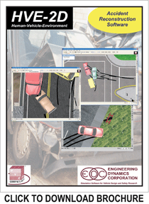
HVE-2D 是一個集成環境,用於設置和執行廣泛驗證的重建和仿真模型,如EDCRASH和EDSMAC4,以研究機動車輛碰撞。這些模型讓用戶重建和模擬涉及一 個,兩個或任何數量的車輛的碰撞的一套車輛碰撞模擬軟體
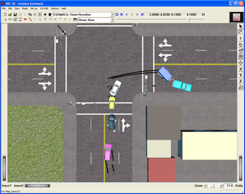
車輛編輯器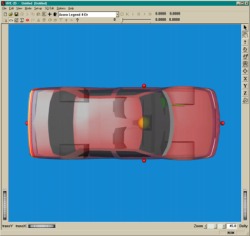 |
環境編輯器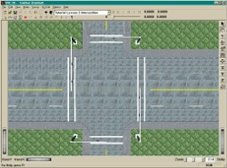 |
事件編輯器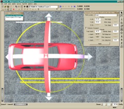 |
播放編輯器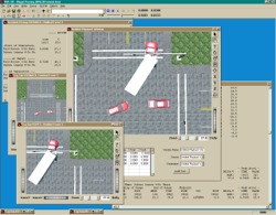 |

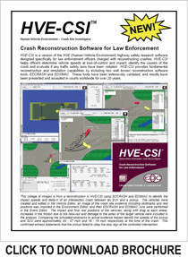
HVE-CSI 是一個獨特的版本,直接著眼於執法人員的需求。重建的結果有助於識別諸如速度過快,失控和無法遵守交通控制設備等因素。它的易用性和極其實惠的價格使 HVE-CSI成為整個碰撞重建團隊的一個有吸引力的選擇。
車輛編輯器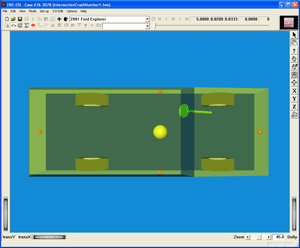 |
環境編輯器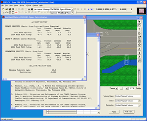 |
事件編輯器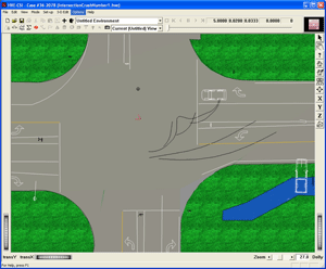 |
回放編輯器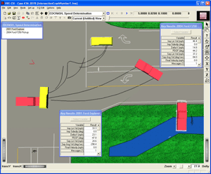 |


