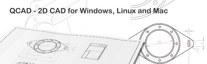
QCad 是一個用於二維設計及繪圖的電腦輔助設計(computer-aided design, CAD)軟體,支援Linux、Mac OS X、Unix及Microsoft Windows作業系統。使用QCAD,您可以創建技術圖紙,例如建築物,室內設計,機械零件或原理圖和圖表的平面圖。QCAD的源代碼是根據流行的開源許可證GPL版本3(GPLv3)發布的。
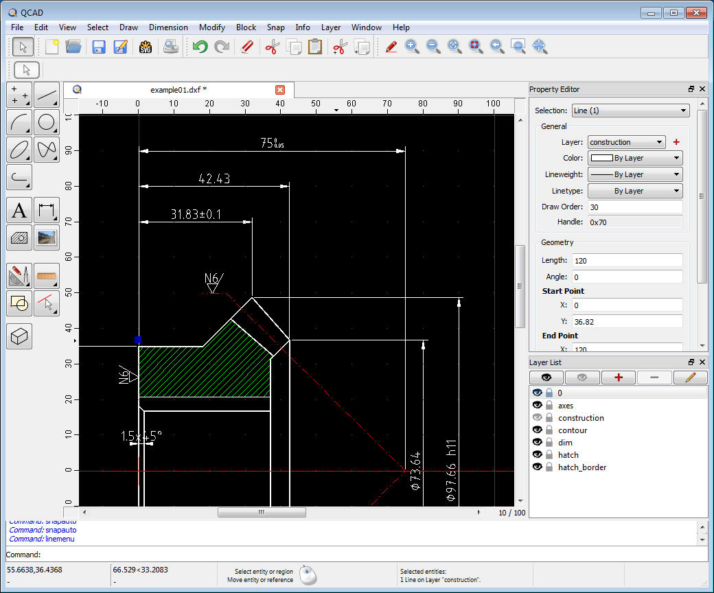
QCAD在設計時考慮了模塊化,可擴展性和可移植性。但是人們最常注意到的QCAD是其直觀的用戶界面。QCAD是每個人都易於使用但功能強大的2D CAD系統。您不需要任何CAD經驗即可立即開始使用QCAD。
主要特點
- Layers
- Blocks(分組)
- 包括35種CAD字體
- 支持TrueType字體
- 各種公制和英制單位
- DXF和DWG輸入和輸出
- 按比例影印
- 在多頁上影印
- 超過40種建築工具
- 超過20種修改工具
- 點,線,弧,圓,橢圓,樣條線,折線,文本,尺寸,剖面線,填充,光柵圖像的構造和修改
- 各種強大的實體選擇工具
- 對象捕捉
- 測量工具
- 具有超過4800個CAD零件的零件庫
- 非常完整且功能強大的ECMAScript(JavaScript)腳本編寫界面
- 命令行工具(dwg2pdf,dwg2svg,dwg2bmp等)
- QCAD / CAM:
- G-Code export
- Nesting
QCAD Professional
This feature list applies to the current version of QCAD Professional.
Features in blue italic are available in QCAD Professional only.
- Supported file formats:
- DWG and DXF: read and write support for format versions:
- R2.5 (read only)
- R2.6 (read only)
- R9 (DWG read only)
- R10 (DWG read only)
- R11
- R12 (LT2)
- R13
- R14 (LT98/LT97)
- R15 (2000/LT2000)
- R18 (2004/LT2004)
- R21 (2007/LT2007)
- R24 (2010)
- R27 (2013)
- R32 (2018)
- DGN (Microstation)
- read only
- DWF
- read only
- DXF version R15 (2000) [QCAD Community Edition]
- CXF font format
- reading for use as font
- opening and editing
- saving
- BMP, JPEG, PNG, TIFF, ICO, PPM, XBM, XPM
- import bitmaps into drawing
- export drawing as bitmap
- SVG
- import (only basic geometry is imported)
- export drawing as SVG
- export dashed lines broken up into path (identical look)
- export dashed lines as lines with dash pattern (rendered by SVG viewer)
- embed or link bitmaps
- PDF
- export drawing as PDF
- export drawing on multiple pages
- DWG and DXF: read and write support for format versions:
- Multi-document interface with tabs
- Layer support
- Block support (grouping)
- Default template to use for new drawings
- 24bit Colors
- (available in all editions but not writable to DXF in the QCAD Community Edition due to DXF 2000 format restrictions)
- 24 different line widths
- 47 built in linetypes
- includes 9 complex linetypes with text / shapes
- extendable through .lin files, .cxf files
- 35 CAD optimized line fonts
- extendable through .cxf files
- ISO 3098 font (osifont)
- All installed scalable system fonts (e.g. TTF) available for texts
- Unlimited undo / redo
- Clipboard functions (copy, cut, paste, duplicate)
- rotate, scale, flip while pasting
- paste multiple instances along entity (with distance or number)
- Font substitution
- Supported units:
- Metrical: Nanometer, Millimeter, Centimeter, Decimeter, Meter, ...
- Imperial: Inch, Foot, Mile, Microinch, Mil, Yard
- other: Angstrom, Micron, Astro, Lightyear, Parsec
- Printing
- printing to scale (e.g. 1:2, 1:100, ..)
- print preview with paper selection
- individual printer settings for every individual block / layout block
- print drawing on multiple pages (poster)
- print crop marks
- print page tags
- printer calibration
- Construction
- Points
- single points
- N points on a line
- array of NxM points
- Points
- Lines
- with two points
- given absolute angle
- horizontal / vertical
- parallels
- bisectors
- tangents
- orthogonal
- orthogonal to line and tangential to arc, circle, ellipse
- given relative angle
- freehand lines
- Infinite lines (construction lines, XLines)
- Rays
- Arcs
- center, radius, angles
- three points
- two points and radius
- two points and angle
- two points and length
- two points and height
- concentric
- adjacent to existing entity
- Circles
- center, circle line point
- center, radius
- center, diameter
- two points and radius
- two opposed points
- three points
- concentric
- tangential to one entity, through two points
- tangential to two entities, through one point
- tangential to two entities with given radius
- tangential to three entities
- center, two points (minor and major axis)
- center, two points, start angle, end angle
- Ellipses
- center, radii
- center, diameters
- parallel curve to ellipse
- inscribed in quadrilateral
- Splines (NURBS)
- from control points
- degrees 1, 2, 3, 4, 5, ...
- from fit points
- degree 3
- insert fit points
- remove fit points
- closed (periodic), open
- from control points
- Polylines
- line and arc segments
- add / delete nodes
- trim segments
- delete all nodes between two given segments
- create polylines from existing segments
- create polylines from selected segments
- create polyline along selected entities
- create equidistant polylines (offset)
- miter join
- round join
- morph between two polylines
- apply easing curve for interpolation
- interpolate Z linearly
- polylines with individual start / end width per segment
- automatically logically close geometrically closed polylines
- automatically logically open logically closed polylines
- replace arc segments with line segments
- Shapes
- rectangle from two points
- rectangle from size
- regular polygon from center and corner point
- regular polygon from two corners
- regular polygon from center and middle of side
- regular polygon from two opposite middles of sides or corners
- star shape
- Rings
- ring from inside and outside diameter
- Texts
- fonts
- ISO, ISO cursive, Courier, Romans, ... (35 CAD fonts included)
- all installed system fonts (TTF, OTF, ...) available for text entities
- alignments: left, right, centered
- vertical alignments: top, bottom, middle
- Unicode support (Japanese, Chinese, German umlauts, ...)
- bold, italic, underlined, subscript, superscript
- backward text
- upside down text
- fonts
- Dimensions
- aligned
- linear (rotated)
- horizontal / vertical
- radius
- diameter
- angles
- arrows (leaders)
- use arrows or architectural ticks (45 degree lines)
- automatic label or fixed label
- apply individual linear scale factor to dimension entities (for detailed views at different scale)
- configurable dimension font
- Hatch
- 68 patterns (extensible by the user supplied .pat files)
- adjustable pattern scale and angle
- solid fill (color fill)
- create hatch from selected, trimmed boundary
- create hatch from segments (untrimmed boundary)
- Raster Images (bitmaps)
- insertion of bitmaps
- adjustable scale, rotation angle
- adjustable transparency
- Block Inserts
- Insert array of blocks
- Viewport
- Add viewport
- Modification
- move / copy
- rotate
- scale
- mirror
- move and rotate
- rotate and counter-rotate
- align reference points
- offset
- to lines, arcs, circles, ellipses
- to multiple polylines
- to polylines
- miter join
- round join
- trim to entity
- trim by amount
- bevel
- round
- divide
- break out segment
- of lines, arcs, circles, ellipses
- of polylines and splines
- break out segment manually
- break out gap
- auto trim (trim / extend to closest intersections)
- stretch
- explode
- ellipses into polylines with arc segments
- splines into polylines with tangentially connected arc segments
- multi-line or formatted text into simple, single line text blocks
- texts into polylines with line and arc segments
- dimensions into lines, texts
- block references
- hatches
- edit texts
- scale text heights
- delete
- move to background / foreground
- align
- detect duplicate entities
- detect zero length entities
- split entities into equal parts
- search / replace in text entities
- clip selection to rectangular area / clear rectangular area of selection
- modify properties of single or multiple entities with property editor
- property painter (copy properties between entities)
- Selection
- selection modes
- replace selection
- add to selection
- remove from selection
- intersect with current selection
- all / nothing
- single elements
- rectangular areas
- polygonal areas
- connected elements (contours)
- elements intersected by a selecting line
- invert selection
- select layer
- select all visible entities
- select entities based on type and / or properties
- select desired entity from multiple overlapping entities using alt-click
- selection modes
- Snap (used to position the mouse cursor to an exactly defined location)
- free
- snap to grid
- snap to endpoints
- snap to points on entities
- snap perpendicular
- snap tangential
- snap to center points
- snap to middle points
- snap to middle between two given points
- snap to reference points
- snap to points with given distance to end point
- snap to intersections
- snap to intersection point of two selected entities
- auto snap
- location defined by entered co-ordinates
- relative/absolute/cartesian/angular, surveyor (N12D34'56"W)
- restrict snap location horizontally, vertically, orthogonally
- lock current snap
- Block tools
- block list as dockable widget
- add new empty block
- create block from selection
- edit block
- copy block
- hide individual blocks
- insert block into drawing
- nested blocks
- remove block
- rename block
- purge unused blocks
- block attributes
- adding attribute definitions to blocks
- editing attribute definitions in dialog
- creating attributes when block with attribute definitions is inserted
- editing attributes in dialog
- editing attributes in property editor when block reference is selected
- synchronize attributes of selected block references / all block references with attribute definitions
- Layer tools
- layer list as dockable widget
- add layer
- edit layer attributes
- remove layer
- show only active layer
- hide individual layers
- purge empty layers
- hierarchical layers
- select multiple layers to delete or edit
- Layer states
- add layer state
- activate layer state
- rename layer state
- remove layer state
- View tools
- view list as dockable widget
- save current view with a name
- update view from current view
- delete saved view
- Overlays
- Direction overlay
- Startpoint overlay
- Order overlay
- Measuring tools
- position
- relative position
- polar position
- relative polar position
- distance between two points
- distance between an element and a point
- angle between two lines
- total length of selected entities
- polygonal area / circumference
- arc, circle, ellipse area
- optionally add measured results to drawing
- Zoom tools
- auto zoom
- zoom in / out (mouse wheel or buttons / hotkeys)
- panning (middle mouse button)
- window zoom
- zoom to selection
- back to last view
- QCAD Library Browser
- over 5000 CAD parts available as free add-ons (screws, nuts, symbols, ...)
- insert parts into the drawing
- adjust angle and scale
- flip
- extensible with user defined drawings and symbols (DXF, DWG, SVG)
- ECMAScript interface
- creation and modification of entities
- create new, interactive CAD tools to integrate into QCAD
- create command line or GUI tools based on QCAD technology
- script shell
- almost entire Qt API available
- SQL database connectivity
- networking
- WebKit
- Multimedia
- XML
- user interface (Widgets)
- Command line tools
- bbox
- print minimum and maximum extents and size of a given drawing to stdout
- bbox
- dwg2dwg
- batch convert between different releases of DXF / DWG
- options:
- list supported format release versions
- set dimension font
- change DXF header variables (DIMTXT, DIMEXE, ...)
- dwg2pdf
- batch convert CAD drawings (DXF, DWG) into PDF
- options:
- print given block
- list paper sizes
- set paper size
- set paper orientation
- substitute fonts
- grayscale
- monochrome
- export given list of layers
- auto fit to paper
- center drawing on page
- list available printer names
- set offset of drawing
- print to a given or the default printer directly
- set drawing scale
- set point size
- set minimum line weight
- auto page orientation
- dwg2svg
- batch convert CAD drawings (DXF, DWG) into SVG
- options:
- export given block
- set page margins
- export points as circles or crosses
- set decimal places for output
- substitute fonts
- export given list of layers
- open SVG after conversion
- set scale
- set minimum line weight
- dwg2bmp
- batch convert CAD drawings (DXF, DWG) into bitmaps (PNG, JPEG, TIFF, ...)
- options:
- set background color
- antialiasing
- export given block
- export given list of layers
- color correction
- substitute fonts
- set quality (JPEG)
- set resolution
- set width / height
- grayscale
- monochrome
- set margins
- zoom to given window
- draw origin
- dwgmapconvert
- batch convert CAD drawings (DXF, DWG) from one coordinate reference system (CRS) to another
- options:
- input CRS
- output CRS
- segment length (when splitting up lines and arcs to maintain correct curvature)
- retain texts (don't split up texts and only transform text label position)
- dwg2maptiles
- batch convert CAD drawings (DXF, DWG) into map tiles for use with online map software such as leaflet.js
What are the minimum system requirements for running QCAD on platform XY?
The CPU and RAM requirements depend very much on the complexity of the drawings you want to create, view and edit.
For simple drawings (a few thousand objects) the recommended minimum requirements for running QCAD 3 on your operating system are:
- Windows Vista, 7, 8, 8.1, 10, 11:
- 260MB disk space
- 1024x768 pixel screen resolution
- 1GHz or faster 32-bit (x86) or 64-bit (x64) processor
- 2 gigabyte (GB) RAM
- macOS:
- 260MB disk space
- Any official Intel based or arm64 (M1 or M2, Apple Silicon) Apple computer that runs macOS >=10.7.
- Linux:
- 260MB disk space
- 800x600 pixel screen resolution
- 500MHz or faster 32-bit (x86) or 64-bit (x64) processor
- 500MB RAM
- The actual requirements may also depend on the window manager you are using (KDE, Gnome, etc) as well as installed background services, etc.
Symantec Norton recommends not running your installer
We usually do not white list our software installers with Symantec since it is a long and tedious process (several weeks). By the time Symantec would approve one version of our installer, we have usually released one or two new ones already.
QCAD/CAM
Computer-Aided Manufacturing (CAM) with QCAD/CAM
QCAD/CAM is QCAD Professional with a CAM (Computer-Aided Manufacturing) module. The QCAD/CAM software includes every tool and feature that QCAD Professional has - but in addition it also has some CAM specific tools to export drawings to machine readable file formats such as G-Code. Such files are usually used to control computer controlled machines (CNC) such as milling machines, engraving machines, LASER cutting machines, plasma cutting machines or water jet cutting machines.
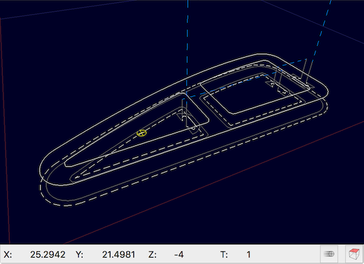
Maximum Flexibility
While QCAD/CAM is specialized in generating CAM specific output for use on a CNC machine, it can be configured to generate virtually any output from any given CAD file. This is made possible through our new ECMAScript based output configuration. The output can not merely be configured - instead, the output filter is programmed in ECMAScript. This opens a vast number of possibilities for QCAD/CAM users. The output can be configured to produce G-Code, G-Code dialects or other open or proprietary, even binary formats. If the specification is known, it can be produced.
Main Features
QCAD/CAM adds the following features and tools to QCAD:
- CAM tool management
- Adding, editing, removing tools (e.g. mills)
- CAM toolpath management
- Creating profile toolpaths with radius compensation, lead in/out, overcuts, multiple passes, etc.
- CAM Export
- Export CAD drawing to configurable CAM output (for example G-Code)
- Interpolations
- Interpolate splines as tangentially connected arc segments within a given tolerance
- Interpolate ellipses as arc segments
- Interpolate TrueType font texts as arcs and line segments
- Interpolations
- Gerber format import (GBX, RS274X)
- G-Code import
- True shape nesting